Engine Intake Part Performance Improvement using 3D Printing
Technology.
(or)
Additive Manufacturing In Formula Student Class 1 Racing Car.
Synopsis/Abstract ABOUT FORMULA STUDENT Event
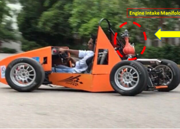
Formula Student is an international engineering design competetion first held by the Society of Automotive Engineers in 1979.There are participants from over 20 different countries and over 600 universities. The goal is to develop and provide a platform for student engineers to experience, build, and learn. It offers a unique way to test students' theoretical knowledge in a practical context. Students gain and develop skills such as enginering, project management and team work. Points are earned in a series of off track, "Static" events, and on track, "Dynamic" events. The team with the most points at the end of the completion wins. Formula Student Case 1Racing car Developed by the student of the renowned engineering college in Hyderabad, Chaitanya Bharathi Institude Of Technology (CBIT) and Engine Intake part with Revised design and manufactured by 3D Foregoer using 3D Printing Technology.
Engine Intake Manifold:-
- 1. The primary function of the intake manifold system is to deliver combustion air to the engine. The geometric design of the intake system affects the volumetric efficiency of the engine, and thus directly affects the performance of the vehicle.
- 2. There are several objectives to consider when designing an intake manifold:
- Minimize pressure loss, as pressure loss results in a decrease in output power.
- Maintain equal static pressure distribution in the plenum, as this will cause the cylinders to pull the same vacuum, thus leading to even flow in each cylinder.
- Minimize bends and sudden changes in geometry, as these geometric affects can cause pressure loss.
- Maximize air velocity into the cylinder, as this provides a better mixture of fuel and air, which results in better combustion and performance.
- Minimize the mass of the system; a common goal of every subsystem of the vehicle.
Problem Statement and Solution:
Traditionally, intake manifold systems are manufactured via bonding multiple aluminum pieces (typically either bent pieces of aluminum tubing or cast aluminum components) together with multiple welds.
Due to the inherent geometric limitations imposed by the existing manufacturing process (bending and welding), the team found it difficult to design and fabricate a system in which (i) pressure losses were kept to a minimum and (ii) equal charge was provided to each cylinder.
So, CBIT’s students approached 3D FOREGOER for additive manufacturing solutions for the Engine Intake Manifold.
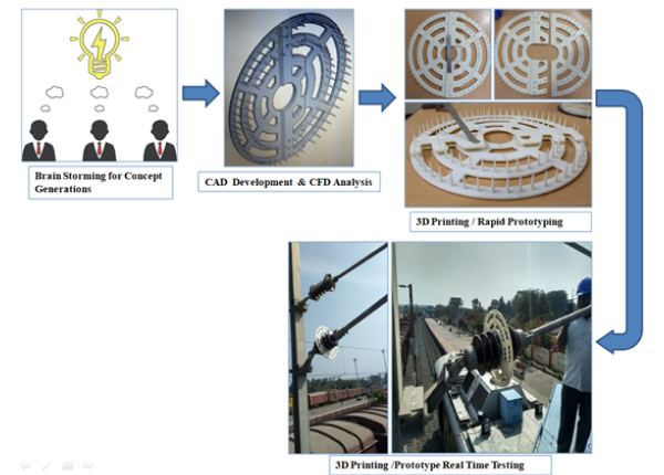
The 3D FOREGOER Team analyzed the initial CAD design along with the 3D printed model of the Engine Intake Manifold and shared design inputs based on Design for 3D Printing concepts with the project team. This ensured that the 3D printed model could withstand vibrations during the high-speed movement of the Formula racing car.
Why 3D Printing :
When there is a less quantity requirement, conventional method for manufacturing will be costly for that product, but 3D printing is suitable for manufacturing of single unit of part. With 3D printing improvement to machine, speed adjustment and also some changes to product design can be made instantly, while in conventional method it can take several week or months to make changes and then production will start. So manufacturing of the engine intake part with 3D printing is best solution to improve its performance.
Material used and Analysis done for Engine Intake Printing:
As strength is the main requirement for engine intake part, 3D foregoer used ABS material for 3D printing. As per design of Engine Intake part provided by the CBIT students, part printing process completed and sent for testing but it failed due to its low strength.
Again 3D foregoer team did research for solution. They did FEA (Finite Element Analysis). FEA is computerised method for predicting how a product reacts to real world forces, vibrations, heat and other physical effects. FEA Analysis is done to know whether a product will break or work the way it was designed for. After FEA analysis, 3D Foregoer suggested to add ribs to design of Engine Intake part on its periphery to have optimum strength to handle pressure and vibrations during real time applications of the moving car. Again it is tested and it successfully worked as per requirement.
3D Printing Machine Used: Aha 3D’s Protocentre 999.
Conclusion:
3D printing is useful for custom made engine intake part which is not manufactured on very high production scale. So, feasible only with 3D printing since cost reduces when quantity increases for conventional method of manufacturing while 3D printing is suitable for manufacturing one quantity parts as well. So 3D printing is best solution for manufacturing of engine intake part.
Wining Story:
The most highlighting feature of Engine Intake part manufacturing with 3D printing is that students of CBIT participated in racing car event organised in UK to represent India.
# class 1 formula racing car event at UK.
This is the most important and proud moment for 3D foregoer team that the engine intake part is presented in racing car event at UK.